WIP - exxos 4MB RAM upgrade on MEGA ST1
Posted: Fri Jul 05, 2019 9:39 pm
I'm trying to upgrade my MEGA 1 with the great Exxos KIT #35.
It's my first attempt so i may have made some mistakes
First the kit out of the box :
Then reading the links provided may help. Yes, well...if you know what is the part number of the components like shifter, glue etc...If you don't have any idea, search the part numbers with google. I found mine here.
The Mega 1 board
Before soldering :
Soldered (part 1)
Once soldered, the pins in the center needs to be trimmed (with cutting pliers) otherwise the 40 pin socket won't fit.
Notice the little component soldered to the pin 40 of the "shifter" (in my case CO70713)
Remove this component from the shifter. We'll need to solder it again to the kit later. Then remove the shifter.
Solder the 40 pins socket to the adapter then put the shifter on it.
Now solder back the [hum...whatever] to the pin 40 of the kit once plugged into the motherboard.
Now you need to find the MMU, for me it was the "C100109". Notice that there is no number "26" or else written on the (or at least on my) my kit so you'll need a bit of imagination to find the good position  Gently push it into position.
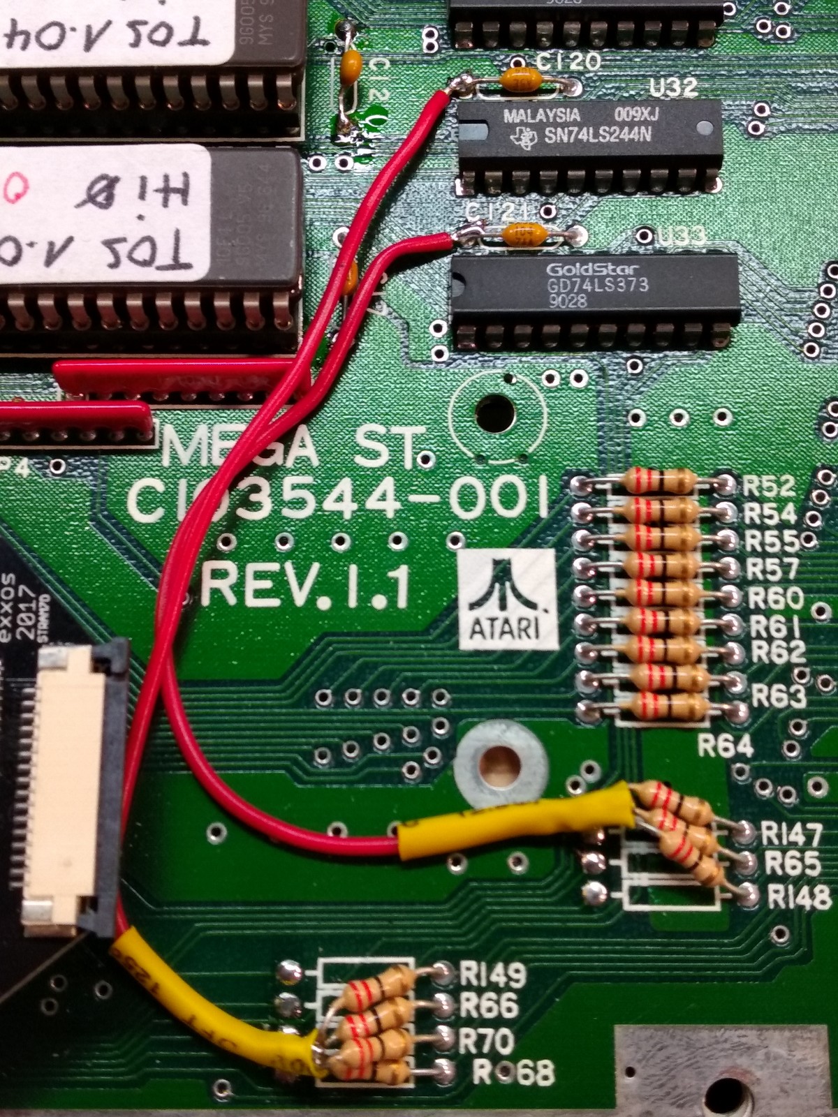
Now add the cable, take care, it's not very long but it fits :
I hope i did everything the right way. If someone can confirm..
Gently push it into position.
Now add the cable, take care, it's not very long but it fits :
I hope i did everything the right way. If someone can confirm..
But now...I'm stuck. I don't find the R59 and i don't know if i need to lift others R#...ie what am i supposed to do ?
If i don't find the good resistances to lift up, i will remove the existing RAM. But it's unclear for me. I mean just removing the 8 RAM chip is enough ? If i remove the 8 (only 8 so i suppose it's 8x128k) do i still have to remove anything else ?
Thanks for your help
It's my first attempt so i may have made some mistakes
First the kit out of the box :
- 20190705_184518.jpg (238.06 KiB) Viewed 3807 times
The Mega 1 board
- 20190705_184546.jpg (297.54 KiB) Viewed 3807 times
- 20190705_184940.jpg (240.69 KiB) Viewed 3807 times
- 20190705_195829.jpg (194.06 KiB) Viewed 3807 times
Notice the little component soldered to the pin 40 of the "shifter" (in my case CO70713)
- 20190705_200333.jpg (254.03 KiB) Viewed 3807 times
- 20190705_201210.jpg (255.3 KiB) Viewed 3807 times
- 20190705_203907.jpg (153.58 KiB) Viewed 3807 times
- 20190705_204714.jpg (207.62 KiB) Viewed 3807 times
- 20190705_205734.jpg (269.7 KiB) Viewed 3807 times
- 20190705_210257.jpg (188.55 KiB) Viewed 3807 times
- 20190705_210627.jpg (316.96 KiB) Viewed 3807 times
But now...I'm stuck. I don't find the R59 and i don't know if i need to lift others R#...ie what am i supposed to do ?
If i don't find the good resistances to lift up, i will remove the existing RAM. But it's unclear for me. I mean just removing the 8 RAM chip is enough ? If i remove the 8 (only 8 so i suppose it's 8x128k) do i still have to remove anything else ?
- 20190705_211724.jpg (263.02 KiB) Viewed 3807 times